Manufacturers have long relied on CAM, or computer-aided manufacturing, systems to command automated machine tools and shape the toolpaths. Industries as diverse as aerospace, automotive, medical, as well as consumer electronics incorporate CAM systems for various purposes. In particular, zirconia is a widespread material to carry out milling operations within this machinery.
When selecting a CAM system for zirconia milling, a few factors should be taken into account. For starters, the size of your desired material plays a key role – zirconia is obtainable in different sizes ranging from minuscule pellets to robust blocks. What’s more, its considerable hardness necessitates a CAM system that is suited to cut hard materials. Lastly, the type of milling operations must be taken into consideration; ball milling, end milling and face milling being some of the most employed operations when dealing with zirconia.
After determining the size, hardness, and type of milling task, the next step is selecting the suitable CAM system. There are numerous CAM systems available, so it is essential to choose one that works harmoniously with the milling machine. Most of these systems are devised to accommodate particular milling apparatuses, so care should be taken to guarantee attainment of compatibility between the CAM system and the milling device. Moreover, the CAM system ought to generate the toolpaths needed to execute the milling operation efficiently.
After selecting a CAM system, the process of outlining the instructions for the milling machine to eliminate material from the workpiece commences. These toolpaths can be either manually formulated or automatically churned out by the CAM system. Manual instructions are generally employed when performing straightforward milling operations, while automatic ones are meant for tasks that require a higher level of complexity.
Subsequent to deciding upon the appropriate toolpaths for the milling machine, stocking it with the necessary implements becomes a necessary action. The variety of tools needed will obviously differ depending on the type of milling operation being conducted – such as for example end milling tools vs face milling tools. Therefore, it is important to ensure that the milling machine is loaded with the definitive and accurate equipment before commencing the project.
After arming the milling device with the specified tools, the following phase is calibrating the settings for the milling activity. The exact modifications depend on the sort of milling endeavor – for instance, end and face milling command two distinct feed speed and rate. This distinction is also evident in the depth and width of each cut.
After the specs have been robustly set, the gears can start to shift. A milling machine is then turned on and prompted to continue by the CAM program. The mill will progress until a shape that satisfies the original specifications is achieved.
After the milling process is finished, the final stage is to detach the machine. The removal strategy varies in accordance with the milling task that has been executed. Face milling operations usually involve the use of a vise to secure the job piece in place,unlike end milling operations which do not expect use of a vise.
Once the milling machine has been unloaded, the workspace needs to be thoroughly tidied. Any shavings or particles that may have been spread due to the milling process should be swiftly swept up. Making sure to clear the area of residual scraps is essential in guaranteeing a successful next milling operation can be carried out.
Related Product
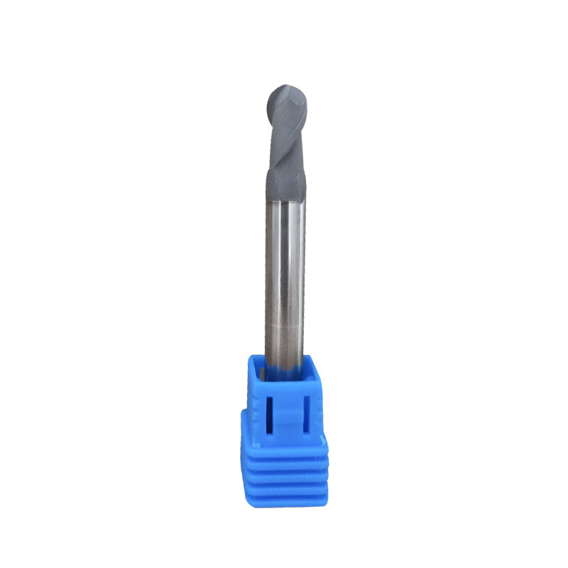
Diamond Coating Round Diamond Cutters
Product Information Origin Tianjing, China Series U Series Brand MSK Cutting Edge Form Helical Structure Ball Diameter (Mm) 3 Material Carbide Minimum Cutting Diameter At Th […]
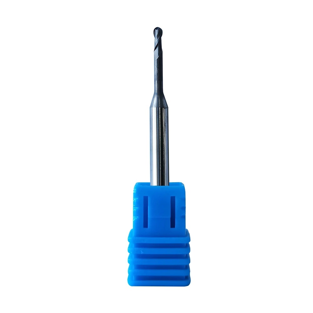
Supply Roland DLC Zirconia Burs
Product Information Origin Tianjing, China Series Dental Bur Brand MSK Cutting Edge Form 2 Blade/3 Blade Ball Diameter (Mm) 0.6, 1, 2 Material Very Fine Grained Cemented Car […]
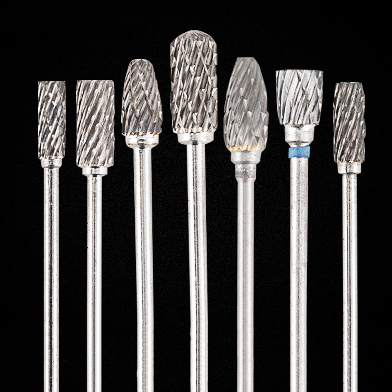
HP Deburring Carbide Burs
Product Information Brand MSK Material Tungsten Steel Model Grinding Head Custom Processing Yes Feature: The dental grinding head is made of tungsten steel with stabl […]
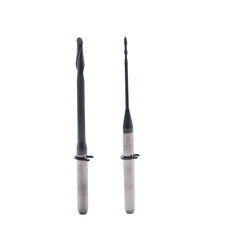
Dental CAD/CAM Milling Burs
Product Information Origin Tianjing, China Material Stainless Steel Brand MSK Applicable Machine Tools A Variety Of Options Custom Processing Yes Whether To Coat No Is It a […]
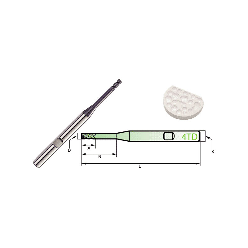
Carbide Roland CAD/CAM Burs
Product Information Origin Tianjing, China Brand MSK Number Of Blades 4 Product Name Dental Special 4-Blade End Mill Model D Number Of Blades Z X N L d 4TD2060HB 2 4 […]
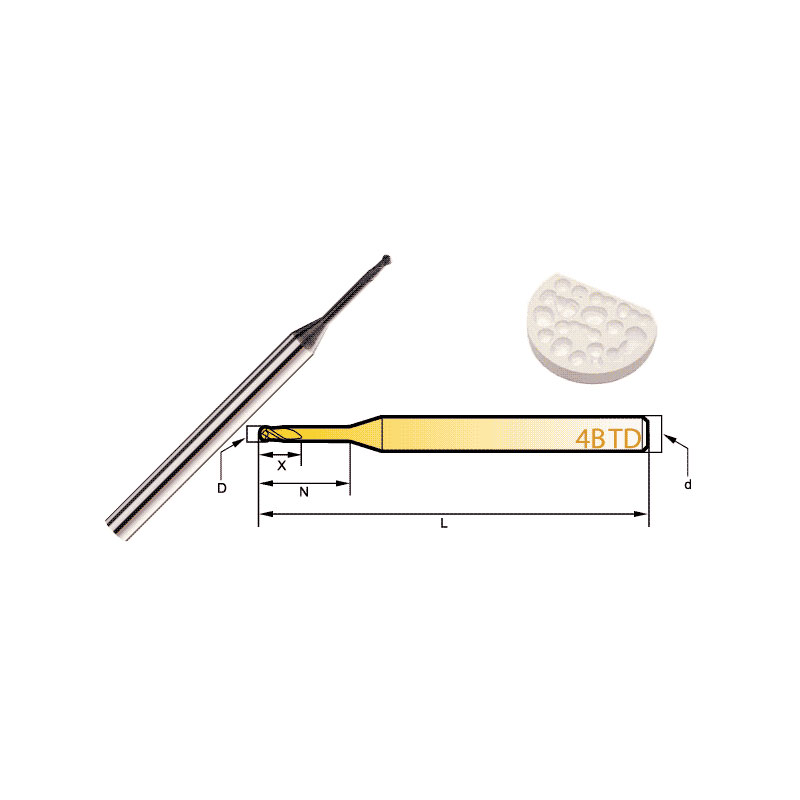
Diamond Bur Ball Round
Product Information Product Name Dental 4-Flute Ball End Mill Brand MSK Model D Number Of BladesZ X N L d 4BTD2060 2 4 6 6 50 3 4BTD2010 2 4 6 10 50 3 4BTD2016 2 4 6 […]
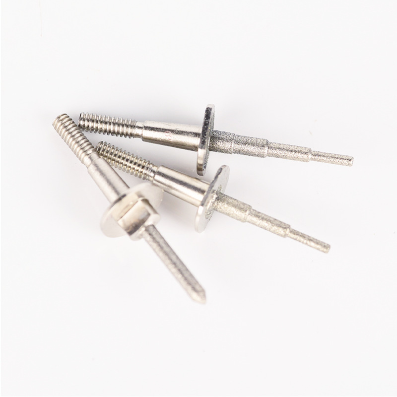
Step Bur Milling Bur Grinder for Glass Cerami
Product Information Origin Tianjing, China Shank Diameter 1.8 (mm) Brand MSK Scope Of Application CEREC3 Grinding Equipment Material Stainless Steel/Carbide Main Sales Areas […]
Post time: 2023-06-27
